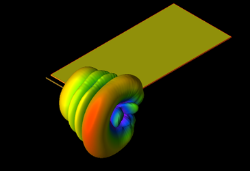
5G/4G Combined Antenna Analysis In A Smartphone Using EM Simulation
Source: Remcom, Inc.

This example uses XFdtd® EM Simulation Software to analyze the performance and interaction of two antenna systems operating at 4G (860 MHz) and 5G (28 GHz) in close proximity in a smartphone design. The 4G antenna is intended to produce a broad pattern for wide coverage while the 5G array should produce narrow beams that can be steered by varying the phasing between elements. The 4G antenna is an inverted-L design and is located at the top of the phone. The 5G antenna array consists of four Yagi-Uda elements that are near the 4G antenna but offset by a conducting block. Download the full paper for more information.
access the Application Note!
Log In
Get unlimited access to:
Trend and Thought Leadership Articles

Case Studies & White Papers

Extensive Product Database

Members-Only Premium Content

Welcome Back! Please Log In to Continue.
X
Enter your credentials below to log in. Not yet a member of RF Globalnet? Subscribe today.
Subscribe to RF Globalnet
X
Subscribe to RF Globalnet
Remcom, Inc.
This website uses cookies to ensure you get the best experience on our website. Learn more
